Regular readers of the blog will perhaps remember the Amdek Mixer mods post a while back (link). It had a very small AC/AC transformer, with a 110v input. I need 220vAC where I live, so I decided to replace the trafo with a DC supply. This has been a huge mission! Read on for part II:

unfortunately after recapping the mixer, the mixer did not perform very long! The second time I switched it on, I got no audio passing through at all. Disappointing. This mixer is a real piece of work to get open and work on it, there are so many separate pieces which interlock. I was gutted it didn't work, and did not look forward to opening it all up again! Anyway, I got on with it : )
The problem was, that the virtual ground design of the PCB/Mixer, had become unbalanced. Apparently this tends to happen very easily with a passive virtual ground design, as this was.
The result is that when the voltage does not balance perfectly across the virtual ground point (which makes a plus and minus voltage from a single sided input supply) you will see instead of eg: +16v and -16v, something like +3v and - 19v. Unless your opamps can handle the maximum output of the PSU (31v in this case, and no, they couldn't!) across the whole opamp, they will be toast, as mine were.
The opamps were JRC4558S (which had a max voltage rating of +18v and -18v) would have been able to cope with 31v/2= +16v and -16v easily. However, they were killed when the voltage slipped out of balance.
I had to find 4 replacements, which proved tricky. JRC4558S is a nine pin package which is not even listed on it's own datasheet! After some searching I read that the KA4558 had the same spec, and probably pinout as the JRC4558S. More datasheet reading later: I could use NJM4558L as a direct replacement, though I had to resort to some pin transposition and flipping the pinout 180 degrees, in order to achieve this.
If you look at the image here, the original 9 pin SIP JRC4558S (on top) has two VCC pins which are bridged (and one is not used in the Amdek design) The replacement (bottom) 8 pin SIP NJM4558L can be used as the pins are perfectly positioned IF you flip pin1 to pin8 and transpose the whole SIP up by one pin placement leaving the pin 9 NC (not connected):

Anyhoo this was only the beginning, as I still had to make a better balanced ground. As I had a DC DC converter in stock, and I needed something in a very small package to fit into the mixer case, I decided to use this. It takes a single sided voltage input and makes +15 and -15v out of it. HOWEVER! I realised after reading the data sheet that without regulators and filtering I would not get a stable, low ripple supply.

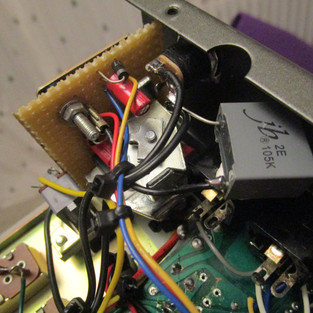
I had just enough space left in the mixer to be able to mount these regulation components in there. The regulation/filter board is mounted where the original transformer was. It takes the +-15v and regulates down to 12/-12v. The DCDC converter is mounted in a free space in between the faders.

There is just enough room to potentially mount some isolation transformers on the outputs, in case there is noise in the future. I've used the mixer, and it is very quiet. However, iso trafos would be a potential great addition later, if necessary.
Some other shots: The mixer is now stable, and working very well.


Comments